Introduction
This project consisted on the development of DRIVERTIVE, DRIVER-less cooperaTIve VEhicle, which aims to advance cooperative automation, bridging the gap between lab demos and real-life implementation. The purpose of this project is to give a general overview of the different designs used to adapt a factory vehicle, with no access to low-level control systems, into a fully-automated cooperative vehicle fit to compete in the GCDC2016. The approach taken was pragmatic: different pre-existing techniques for control, state estimation, data fusion, communication and data degradation were combined and experimentally validated in real-world scenarios, together with other vehicles with different implementations.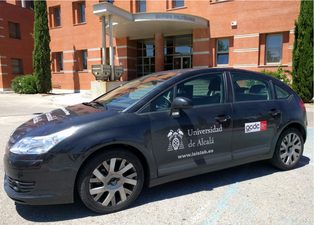
System Architecture
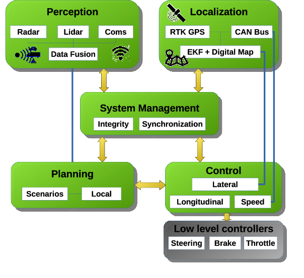
DRIVERTIVE vehicle is a commercial Citröen C4 with automatic transmission modified for autonomous driving. These modifications involve different hardware components which allow automated control of the steering wheel, accelerator and brake. In order to have full control of the vehicle, the three main vehicle actuators needed to be automated: the steering wheel, brake and accelerator. In our specific case, only the accelerator was originally controlled by wire forcing us to use mechanical solutions for automation of the steering wheel and brake.- Steering column A DC motor with a planetary gearhead was connected to the steering column by means of a chain drive. A magnetic clutch is responsible for engagement and disengagement of the DC motor with the chain drive, allowing us to switch between automatic and manual control. The DC motor is controlled by an Easy-to-use POsitioning System (EPOS) with USB interface which implements a position PID controller.
- Accelerator The original by-wire control of the accelerator pedal includes a position sensor mounted on the throttle body. Depending on the opening angle of the accelerator pedal, two different voltage values are applied to the terminals of the vehicle’s electronic control module (ECM); Va and Va/2. Using a DPDT relay between the accelerator pedal position sensor and the ECM the user can define the operating mode (manual or automatic) by physically connecting to the ECM either the pedal position sensor or the analogue signal from a USB data acquisition module.
- Brake The brake pedal is controlled by means of a mechanical system composed of a DC motor, a planetary gearhead, an incremental encoder, and a wire winding pulley. The DC motor is controlled by means of an EPOS with a USB interface which implements a position PID controller. A wire rope is attached between the pulley and brake pedal. Thus, we can press and release the brake pedal according to the control reference.
- Localisation
The localisation subsystem determines the vehicle’s global position with respect to a digital map. In orther for this to happen, an Extended Kalman Filter first combines the positioning information from the RTK GPS and odometry from the vehicle’s CAN bus. Then, the position of the vehicle is matched on a digital map to gather information about its static environment (number of lanes, type of road, orientation, upcoming intersections, speed limits, etc.). On the left, RTK-GPS positions when driving under a toll beach (red) and the ekf positions (blue).
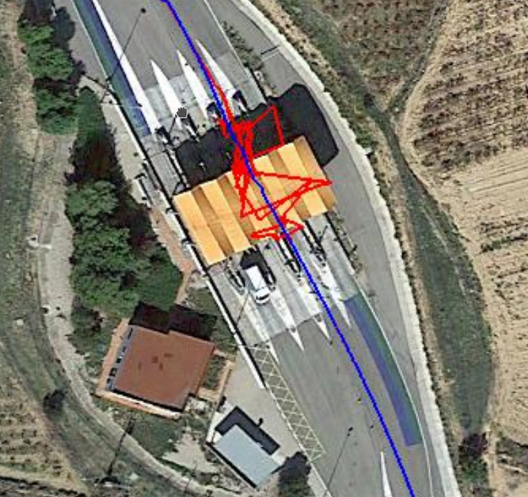 Our EKF was able to accurately maintain the position of our vehicle with small drifts during GPS blackouts due to the presence of several bridges above the road.
- Perception
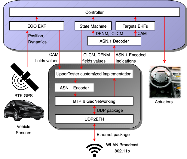
The perception subsystem is responsible for interpreting the information gathered by sensors on board the vehicle and by communications. Its main objective is to maintain an accurate representation of our vehicle’s surroundings. The communications subsystem receives status and environmental information from other vehicles and from infrastructure. The GCDC2016 communications architecture is based on the ITS-G5 V2V standard for V2X communications. This standard uses the GeoNetworking protocol for packet dissemination, the basic transport protocol (BTP) for the transport layer and IEEE 802.11p for the physical layer. This architecture was present in vehicles, as well as in Roadside Units (RSU). Three different sets of messages were used in the competition: Standard Cooperative Awareness Messages (CAM), Decentralised Environmental Notification Messages (DENM) and the non-standard iGame Cooperative Lane Change Messages (iCLCM). CAM messages contain position, geometry,dynamics and some other optional information whilst DENMs are intended to warn of asynchronous events, such as an emergency vehicle approaching, road-works warnings or the presence of a stationary vehicle. iCLCMs were specifically developed for the competition and were used for the interaction protocols in the different iGame scenarios.
 DRIVERTIVE is equipped with a four-layer 3D laser scanner SICK LD-MRS40001 embedded on top of the front bumper, a velodyne HDL-32E Lidar mounted on the
roof and a long-range RADAR Continental ARS 300 mounted on the front of the car.
DRIVERTIVE is equipped with a four-layer 3D laser scanner SICK LD-MRS40001 embedded on top of the front bumper, a velodyne HDL-32E Lidar mounted on the
roof and a long-range RADAR Continental ARS 300 mounted on the front of the car.
- System Management System management supervises the overall functioning of the vehicle, taking care of the information exchange integrity and the synchronisation between different modules.
- Control The control subsystem follows the commands of the planning subsystem. Whilst the longitudinal controller generates accelerations profiles, the speed controller simply follows reference speeds from the longitudinal controller. The lateral controller keeps the car centred and aligned in the corresponding lane and performs the turns and lane changes as ordered by the planning subsystem.
Results
- Longitudinal Controller The longitudinal controller was responsible for maintaining an adequate longitudinal distance in relation to other competitors following, the com- mands of the planning subsystem. The indicated distance to be maintained was defined by the GCDC2016 organisers as follows: a fixed safety distance (r) plus a variable distance which depended on the speed of the host vehicle. This variable distance was defined as a constant (headway time th) multiplied by the speed of the host vehicle (vh). Some examples of the different speed controllers, lateral controller and distance controller can be downloaded here (in red desired, speed or distance. Blue real speed or distance).
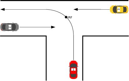
- Intersection Scenario
In intersection scenario 2 competitors and one organisation vehicle had to manage a T-junction. The organisation vehicle always had priority and competitors were required to cross the intersection in as little time as possible, whilst observing maximum speeds and minimum safety distances between one another.
 Some examples of the intersection heats and the information gathered by sensors can be seen here.
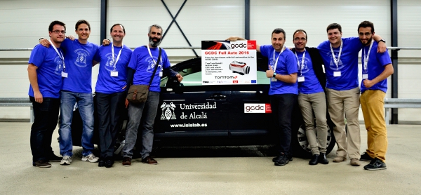
- DRIVERTIVE team wins the Prize for the Best Team with Full Automation in the Grand Cooperative Driving Challenge (GCDC 2016) held in Helmond, The Netherlands, in 28-29 May 2016.
Acknowledgements
This work was supported by Research Grant SPIP2015-01774 "Cooperative UAH Car" (General Traffic Division of Spain).Awards
About
 My name is Ignacio Parra. I´m assistant professor at the Computer Engineering department of the University of Alcalá...
More about me
Links
- ISISlab youtube channel
My research group youtube channel - ISISlab webpage
My research group webpage - Computer Engineering Department
My department webpage - University of Alcalá
My University webpage
Free web templates by TemplatesDock
Tip: rodinne domy
Copyright © 2010 Ignacio Parra